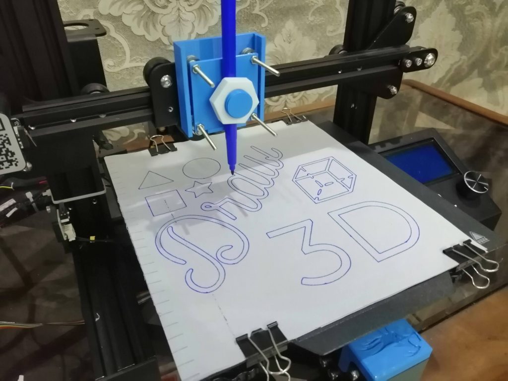
Draw 3D is an open-source extension for Inkscape 0.9 that lets you generate GCODE which will enable your 3D printer to hold a pen and draw.
The original inspiration came from this video by Teaching Tech where he showed the method to generate GCODE using Jtech Laser Inkscape extension. I have modified this extension to make it better and easy to use. I have made the changes in the extension so it can do only one job i.e. generate gcode to let your 3D printer draw on a piece of paper. The hardware setup in this post is demonstrated using an Ender 3 pro but you can use the same idea on pretty much any FDM 3D printer.
Extension Installation
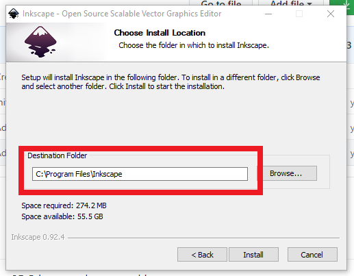
The first step is to download Inkscape 0.92.4 from this link and install it. Note the installation folder while installing. It is important to note use the latest version of Inkscape because the extension is not compatible with that.
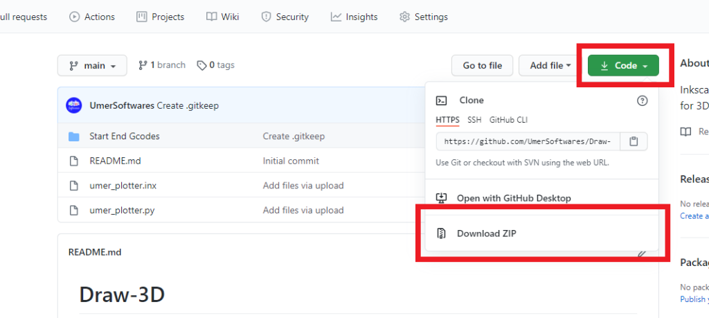
After that go to the github link of the extension and download the code as zip file.
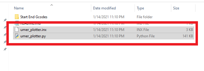
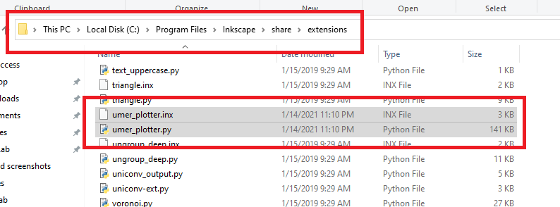
Extract the zip file and copy the two files umer_plotter.inx and umer_plotter.py from the extracted folder.
Go to the {Installation Folder}/share/extensions and move the umer_plotter.inx and umer_plotter.py files to this folder. Remember you noted the installation folder in the first step.
The extension installation on windows is now complete.
Pen Attachment
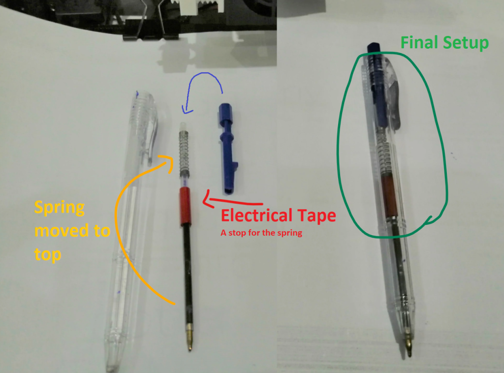
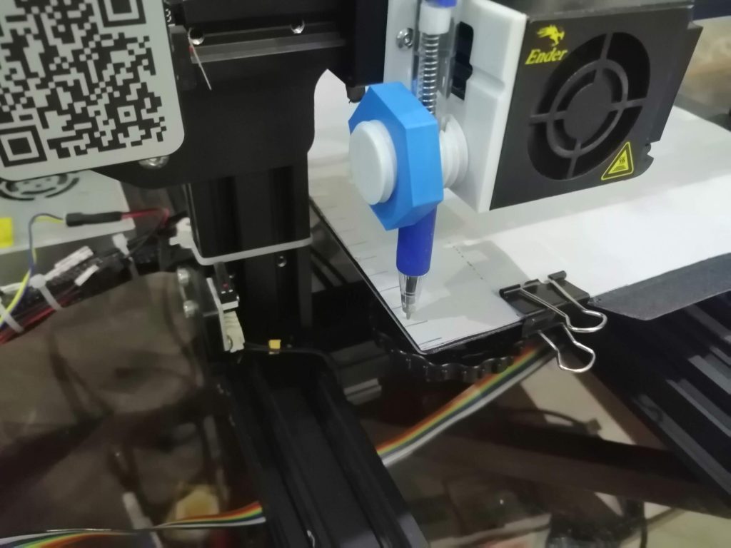
The next step is to attach a pen to the head of your 3D printer. It is better to use a system that can sprint up and down a little bit. I have this small hack that you can do with a ballpoint to achieve that. Put some electrical tape near the middle of the pen’s refill and place the spring over it. Now, when you put it back in the pen, the spring will be pushing the nib down and the nib will be able to sprint a little bit into the pen if some force is exerted on it.
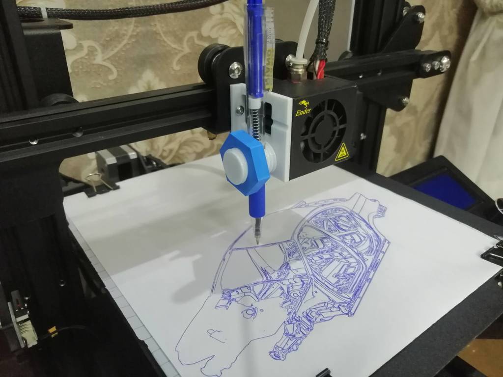
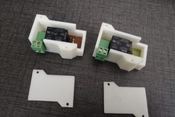
You can mount this pen on a fixed pen holder like this one for my Ender 3 pro
Or you can use a sliding mechanism with a fixed pen.
Here are links to printable pen holders for Ender 3/3pro, CR10 or similar printers designed by me:
You can find many other designs on Thingiverse. Just print a holder and mount a pen on your printer’s head.
Take Measurements
We need to measure a few things because the extension will require these to generate the code for your printer.
First, measure the x and y dimensions of your printer. You can also google the size of the build plate for your printer.
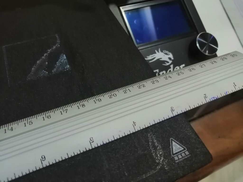
Mount the pen. Attach paper on your bed with binder clips. Then use the move axis menu on your LCD or any other tool such as octoprint or pronterface, move the pen’s nib to the bottom left corner of the paper where you want the drawing to start. Make sure to leave some clearance for the binder clips.
Now, just note down the position of your X, Y and Z axis.
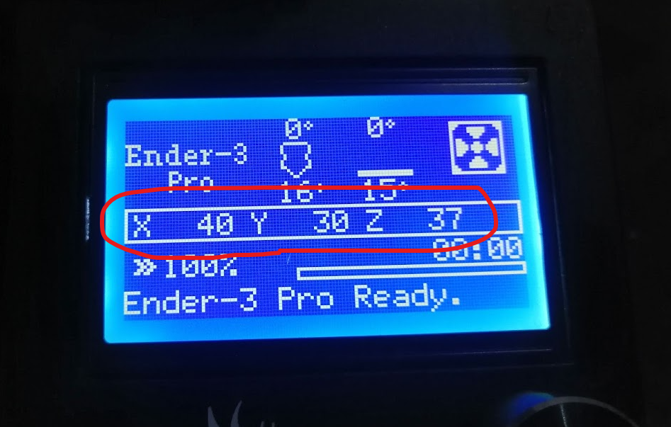
Also, get an estimate of how much you need to raise the pen so that it stops touching the paper. In my case, raising it by 5mm is more than enough.
Plugin Settings
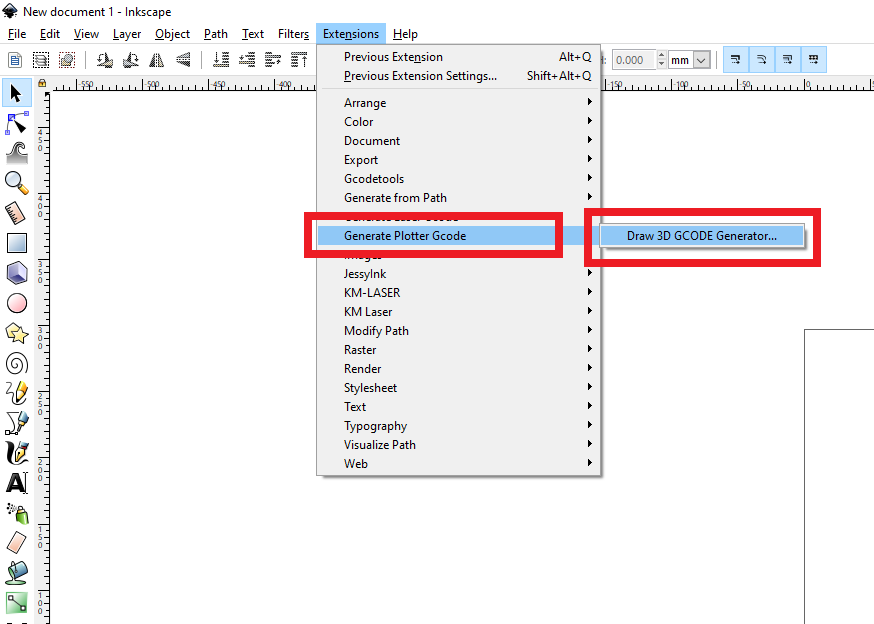
Open Inkscape, go to Extensions > Generate Plotter Gcode > Draw 3D GCODE Generator

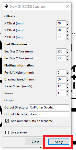
In the next window, you can input the measurements that you have taken in the previous step.
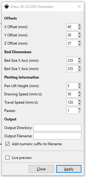
An explanation of all the options is given as follows:
Offsets
- X Offset is the position of the x axis when the pen is just at the bottom left corner of the drawing area
- Y Offset is the position of the y axis when the pen is just at the bottom left corner of the drawing area
- Z Offset is the position of the z axis when the pen is just touching the bottom left corner of the drawing area
Bed Dimensions
- Bed size X axis is the total size of the bed in x axis
- Bed size Y axis is the total size of the bed in y axis
Plotting Information
- Pen Lift Height is the height in z to lift the pen so that it stops drawing
- Drawing Speed is the speed with which the pen moves when it is pushed against the paper
- Travel Speed is the speed with which the pen moves when it is lifted.
- Passes is the number of times it is going to draw the complete drawing. You can increase this value from 1 if the pen does not draw well in one pass.
Output
- Specify the path of the output folder in Output Directory
- Specify the name of the output file in Output Filename option
- Checking the Add numeric suffix to filename will add a 3 digit number at the end of the file so that it is not overwritten by the new one.
Generating GCODE
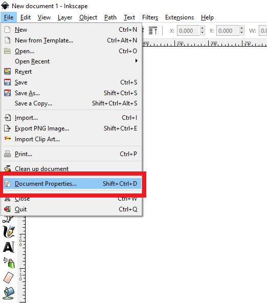
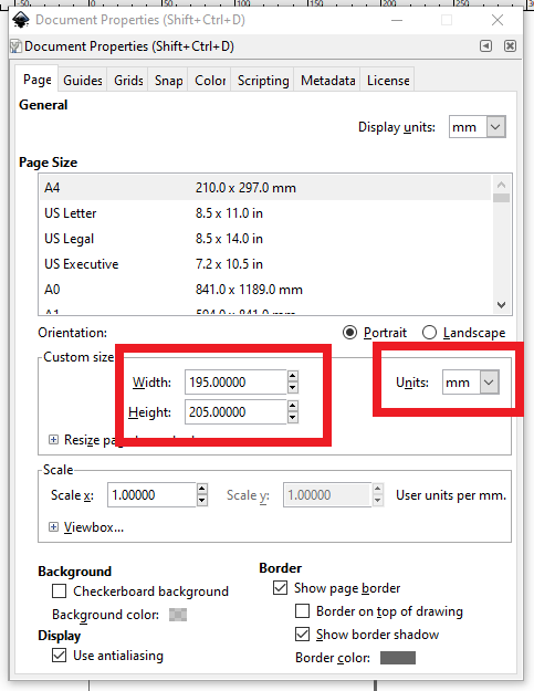
First, set the drawing area size in Inkscape. To do that, go to File > Document Properties
Calculate the x and y drawing size as:
X Drawing Size = Bed Size X axis – X offset
Y Drawing Size = Bed Size Y axis – Y offset
Input the X drawing size in width and the Y drawing size in height. Make sure the units are mm.
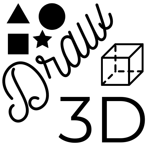
We need to import an image into Inkscape and convert it to vector. You can use the following image to get started.
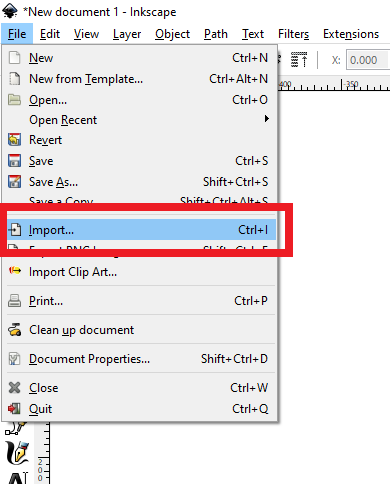
Go to File > Import and import the image into Inkscape
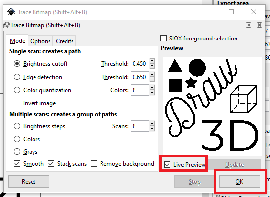
Adjust its size. Then go to Path > Trace Bitmap
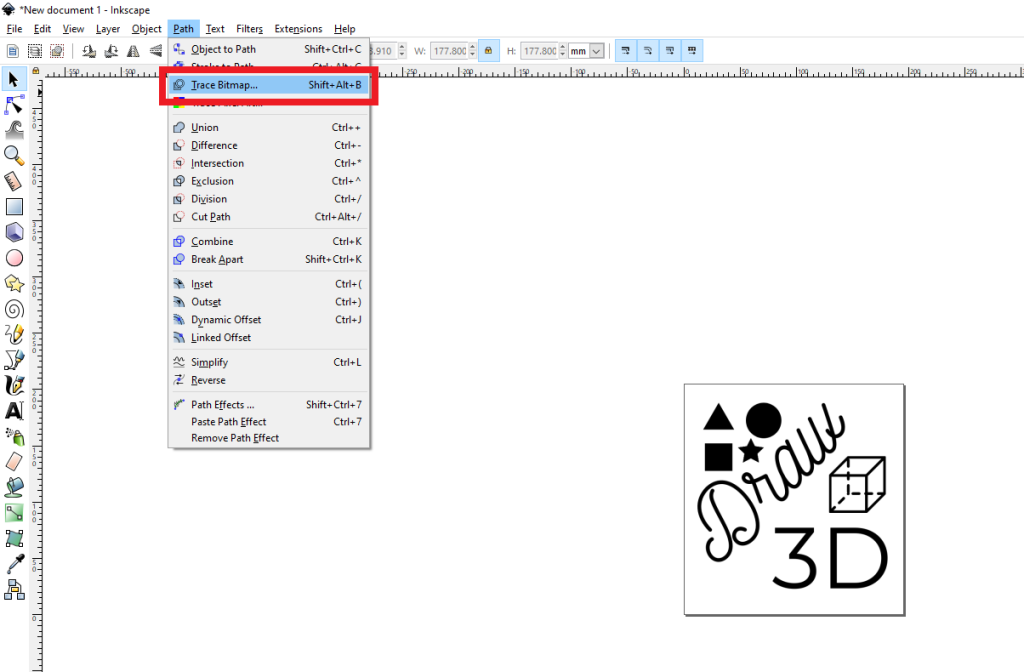
Check the Live Preview button and click OK. Other options remain default.
Now, open the extension, specify the output directory and filename and hit apply.
It can take a few seconds to generate the gcode. Once it is generated, you can run it on your printer that has the pen attached.
There are also some hacks that can be done using custom start and end gcodes with the extension because I have added support for custom start and end gcodes in the extension. Place the start gcode in header_plotter_plugin.txt file and the end gcode in footer_plotter_plugin.txt file. The files need to be in the output directory.
27 Comments
Andrew Williams · January 21, 2021 at 3:16 am
The gcode output tries to cut corners when drawing and sometimes doesnt lift up. In Inkscape, the path appears to be correct, but when its actually compiled it seems to get lost in translation. Ive tried to reinstall both inkscape and the extension but no quick remedies seem to work. Any idea what could be going wrong?
https://imgur.com/a/TEdqWH6
rhigma · March 14, 2021 at 9:32 am
Cura didnt show the draw lines for me either. Try viewing the gcode on https://ncviewer.com/
Danthes · February 3, 2021 at 4:19 am
Que tal amigo, muy bueno tu aporte, oye me pregunto si crees posible crear en la extensión de inkscape que modificaste, hacer que pueda generar código para hacerla compatible con quemado o corte laser, creo que la diferencia entre el plotter y el laser es el código para en vez subir y bajar el lapiz seria apagarlo y prenderlo, espero puedeas hacerlo y compartirlo, gracias.
umer · February 21, 2021 at 5:04 pm
The original extension that I have modified, was for laser. It is called JTech Laser. I have linked it in the article as well.
monosaku · February 5, 2021 at 7:07 pm
this looks very promising! I can’t get it to run though.
With my specific setup (Ender 3 “classic” with silent 4.2.7 Board running latest Creality FW 0.0.6) I can’t run G2/G3 “Arc” gcode.
Is there a way to not produce G2/G3 in the first place but only produce G1 commands?
umer · February 21, 2021 at 5:03 pm
You can reinstall marlin on your board after enabling G2 and G3. As I am not the creator of the extension (I just modified an existing one to suit this application), I don’t know exactly how it is generating gcode so I can not tinker with it.
Lean · February 10, 2021 at 6:06 am
Nice idea! But I reveice this error when I run “apply”
File “umer_plotter.py”, line 54
def bezierslopeatt(((bx0,by0),(bx1,by1),(bx2,by2),(bx3,by3)),t):
^
SyntaxError: invalid syntax
umer · February 21, 2021 at 5:01 pm
You might be using the latest version of inkscape. Please use inkscape 0.92.4 as mentioned in the article.
Kenan Hloubi · February 10, 2021 at 8:50 pm
i have a problem generating the gcode.. i always get this message.
File “umer_plotter.py”, line 54
def bezierslopeatt(((bx0,by0),(bx1,by1),(bx2,by2),(bx3,by3)),t):
^
SyntaxError: invalid syntax
what am i doing wrong ?
thanks!
umer · February 21, 2021 at 5:01 pm
You might be using the latest verison of inkscape. Please use inkscape 0.92.4 as mentioned in the article.
Pedro Alessio · February 17, 2021 at 8:04 pm
Hi there, congratulations for you work. I had this error when I was trying ina a MACOS INKSCAPE 1.0.2
Thank you for your support
File “umer_plotter.py”, line 54
def bezierslopeatt(((bx0,by0),(bx1,by1),(bx2,by2),(bx3,by3)),t):
^
SyntaxError: invalid syntax
umer · February 21, 2021 at 4:59 pm
I have mentioned that it does not work with inkscape 1. Please use the version of inkscape mentioned and linked in the article.
Joe Kusmierz · December 20, 2021 at 5:01 am
Using Mac, it won’t allow you to open that version of Inkscape nor does it even have a dmg file to download. I’m having this same issue as others and would like to know if there’s another way to fix it.
Seth J Ogreenc · February 24, 2021 at 2:56 am
I like your idea and cant wait to see it in action. But I am not sure what to put in the “output directory”. I did not quite understand what you meant by “Specify the path of the output folder in Output Directory”
umer · February 24, 2021 at 6:27 am
Open a folder in Windows File Explorer. From the address bar, copy the address of the folder. It will be something like “C:\Users\something”. You have to put this folder’s address in the output directory.
Roh · March 1, 2021 at 3:25 pm
Hello, nice work. Will you update the plugin to Inkscape’s latest version ?
umer · March 5, 2021 at 6:16 am
No plans yet
Roh · March 1, 2021 at 9:52 pm
Hi. Would it be possible to generate the gcode such that the solid parts in the drawing are actually filled by the printer ?
umer · March 5, 2021 at 6:16 am
Use the KM Laser plugin https://github.com/KnoxMakers/KM-Laser to create a hatch in your SVG. Then use my plugin to generate gcode.
Jaden Moore · March 12, 2021 at 4:52 am
I followed all of the steps, downloaded the linked inkscape, github extensions, moved them to the folder and tested the included image etc. But I get this error code when trying to generate the final gcode: Traceback (most recent call last):
File “umer_plotter.py”, line 3217, in
e.affect()
File “inkex.py”, line 283, in affect
self.effect()
File “umer_plotter.py”, line 3214, in effect
self.laser()
File “umer_plotter.py”, line 3082, in laser
self.check_dir()
File “umer_plotter.py”, line 2606, in check_dir
if self.options.directory[-1] not in [“/”,”\\”]:
IndexError: string index out of range
Any help would be greatly appreciated. Thanks!
umer · March 15, 2021 at 4:04 am
In the output directory field, make sure you have entered the correct folder path. I recommend opening the folder in windows explorer and copy the path from the address bar and paste it into the extension.
Fernando · March 16, 2021 at 8:11 pm
Hi, I followed all steps and did the first drawing with the picture you use. The final drawing doesn’t looks like the original image, it just seems like some random strokes and some shapes. I attach an image of it here. Help pls. Thanks
https://drive.google.com/file/d/17R_HvSlpgZYGcrIkoac0FCOrSmmOeO0Y/view?usp=sharing
umer · April 1, 2021 at 4:51 am
G2 and G3 arc gcodes are not enabled in your firmware. If you can flash the firmware on your board, you can enable arc support in marlin.
I am working on a python script to convert G2 and G3 to normal G1 codes so that the printers that don’t have arc gcodes enabled can also draw.
Fer · April 5, 2021 at 3:14 am
oohhhh, okkk. Flashing the bootloader and firmware and all that stuff is a bit confusing to me, it will be great to have a script like that. Thanks for the support 🙂
Joe · December 20, 2021 at 3:55 pm
Have you written the python script to fix this yet? I’d rather not have to buy an Arduino and flash the firmware just for a little gcode to draw a picture
Aayush Sapra · May 27, 2021 at 7:37 pm
Inkscape crashes every time i try to generate gcod, i have taken care of version and done and verfied the installation acc to the instructions, can you help me.
thatfg · July 17, 2021 at 9:01 pm
I am having the same issue as Andrew W on the first comment. The Gcode appears to generate correct, but the 3D printer does not appear to be able to render the Gcode. I tried printing and there were several issues with my print after using Inkscape and your extension. It does not seem to compile it correctly and I don’t know why that may be. I’m using 19.4 as instructed.
I read the comments and you stated something about G2/3 codes not being supported. Is it possible that you finished your conversion to G1 codes? Thank you.